Prefabricated running track seam layout should be resolved before final cutting and adhesive application. The plan needs to coordinate roll dimensions, surface orientation, track geometry, drainage and event equipment. Curves and runways introduce different fitting demands from a straight training lane. A documented layout helps reduce awkward joints, unnecessary narrow pieces and forced stretching while preserving the approved athletics geometry.
Keywords: running track seam layout, prefabricated track roll plan, curved track installation, long jump runway surface, rubber track joints
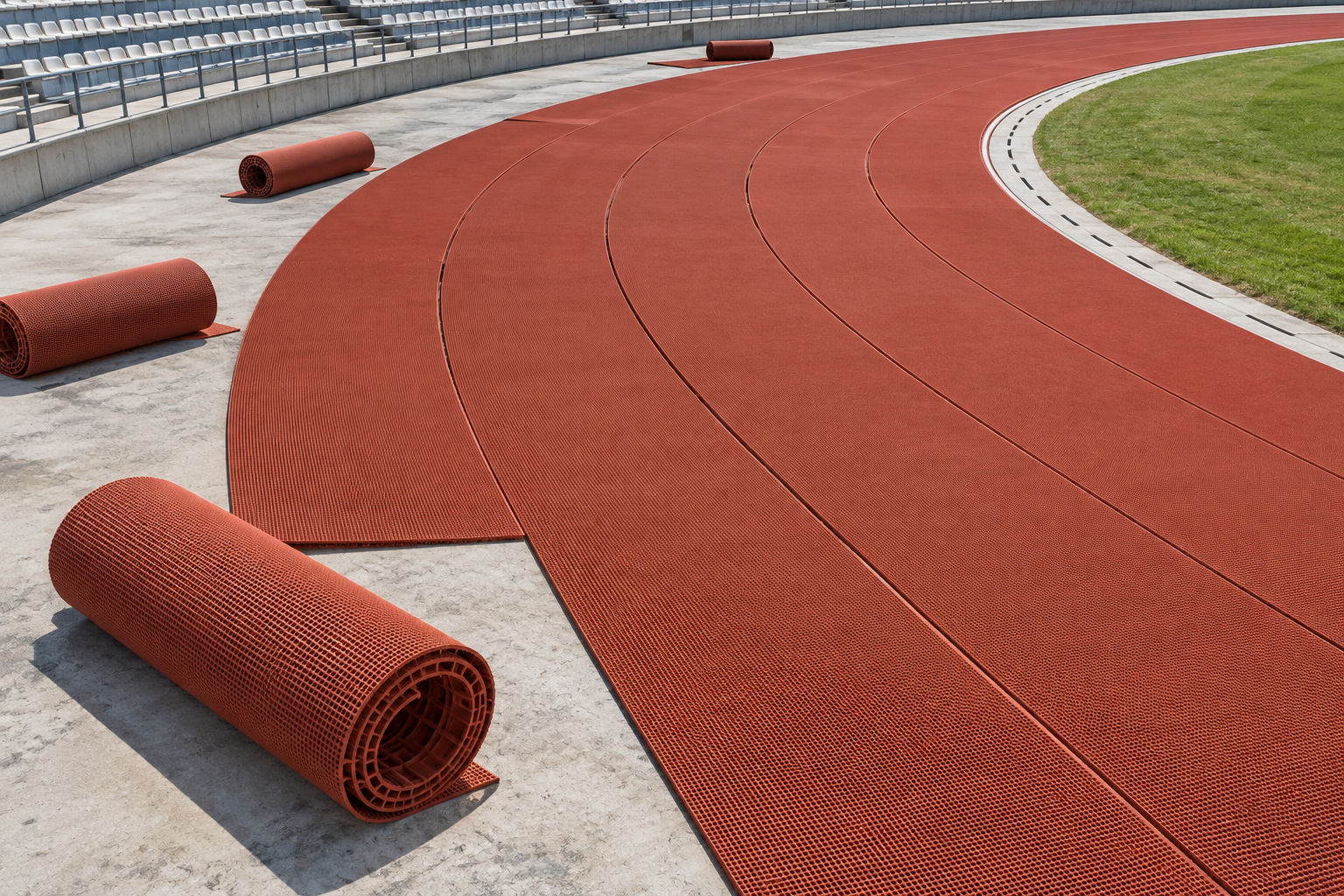
![Prefabricated rubber strips being fitted around the curve of a stadium track]()
Figure 1. Prefabricated rubber strips being fitted around the curve of a stadium track. AI-generated technical illustration.
Begin With the Surveyed Geometry
Use the approved facility drawings and verified site setting-out as the reference. Confirm the relationship between the finished running surface, curbs, drains and event fixtures. Roll width is a material dimension, while lane width and measurement lines are sporting geometry; one does not automatically determine the other.
The World Athletics technical document library provides facility and marking references for relevant athletics projects. The applicable requirements should be established by the designer and project specification. Do not alter an approved lane arrangement simply because a particular roll layout appears easier to install.
Plan Longitudinal and End Joints Separately
Longitudinal joints run along the length of neighboring strips. End joints connect consecutive sheet lengths. Each needs sufficient support, accurate trimming and a compatible bond. Their locations should be shown on the roll plan along with material orientation and roll identities.
For straight sections, align sheets to the agreed layout and use consistent texture orientation where the product requires it. Avoid unnecessary short inserts and narrow slivers. Where end joints can be positioned away from particularly demanding zones without compromising the design, consider that during planning rather than after the adhesive is spread.
![Longitudinal seam aligned with the direction of a straight running lane]()
Figure 2. Longitudinal seam aligned with the direction of a straight running lane. AI-generated technical illustration.
Give Curves Their Own Fitting Method
A straight rectangular sheet does not conform to every curved layout without an approved fitting strategy. Radius, roll dimensions and material behavior influence the cutting and placement sequence. Use the surface manufacturer's curve details and confirm them in a trial area where needed.
Do not stretch the outer edge aggressively to compensate for geometry or force excess material into the inner edge. Such adjustments can leave tension, puckering or inconsistent contact. Check the fit in the conditioned state, trim as specified and confirm support at each joint. The correct method is product- and layout-dependent; a universal radial or staggered pattern should not be imposed without design approval.
Coordinate Runways and Event Fixtures
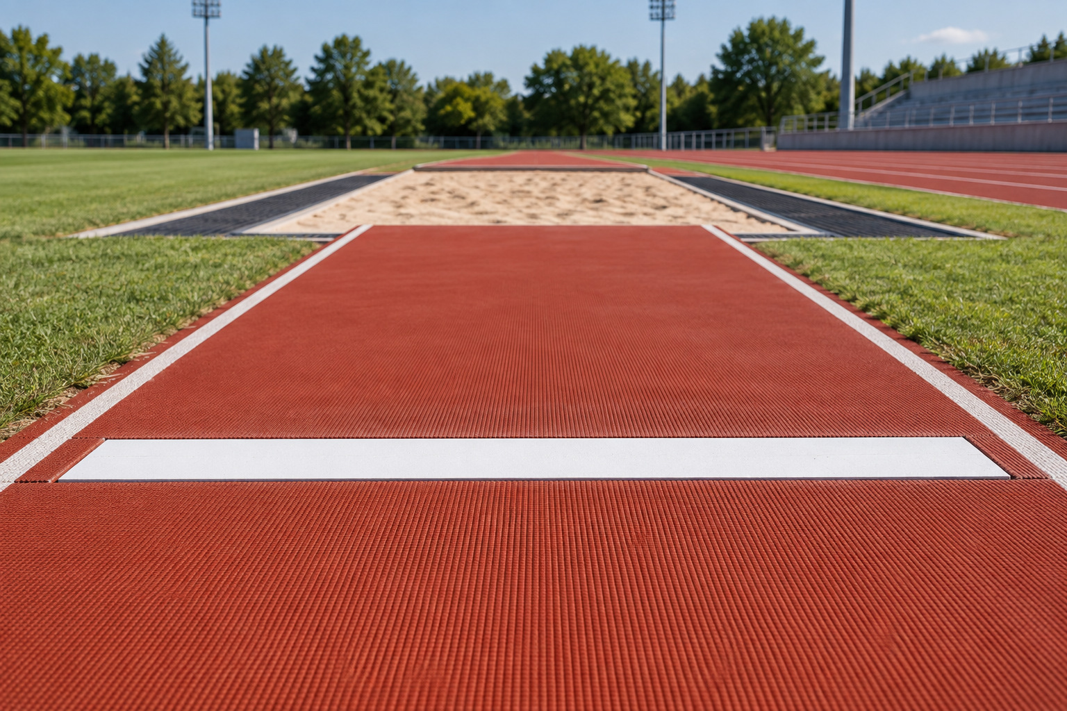
Long jump and triple jump runways need careful coordination with takeoff boards, trays and the sand-pit transition. Other event approaches have their own equipment and loading arrangements. Inspect these interfaces before cutting the adjoining rubber.
| Location | Main coordination issue | Design or installation check |
| Straight lanes | Roll alignment and end joints | Confirm survey references and material orientation |
| Curves | Changing geometry and sheet stress | Approve the fitting method and trial arrangement |
| Jump runways | Takeoff equipment and level transitions | Coordinate trays, boards and finished surface height |
| Drainage edges | Water flow and termination support | Keep outlets functional and edges flush |
| Base movement joints | Structural movement | Use the engineered joint detail |
| Repair interfaces | Existing dimensions and material condition | Confirm compatible matching and support |
![Prefabricated rubber long jump runway meeting a takeoff board and sand pit]()
Figure 3. Prefabricated rubber long jump runway meeting a takeoff board and sand pit. AI-generated technical illustration.
Approve the Dry Fit Before Bonding
Lay out the conditioned material and inspect joint continuity, edge contact and alignment. Confirm that the sequence allows the crew to spread and consolidate adhesive within its working limits. A layout that cannot be installed reliably with the available labor and access needs to be revised.
Record changes to the planned roll arrangement. Where neighboring material comes from different lots, check appearance under consistent lighting before installation. Once adhesive is applied, late attempts to exchange or turn pieces can introduce contamination and exceed the permitted assembly window.
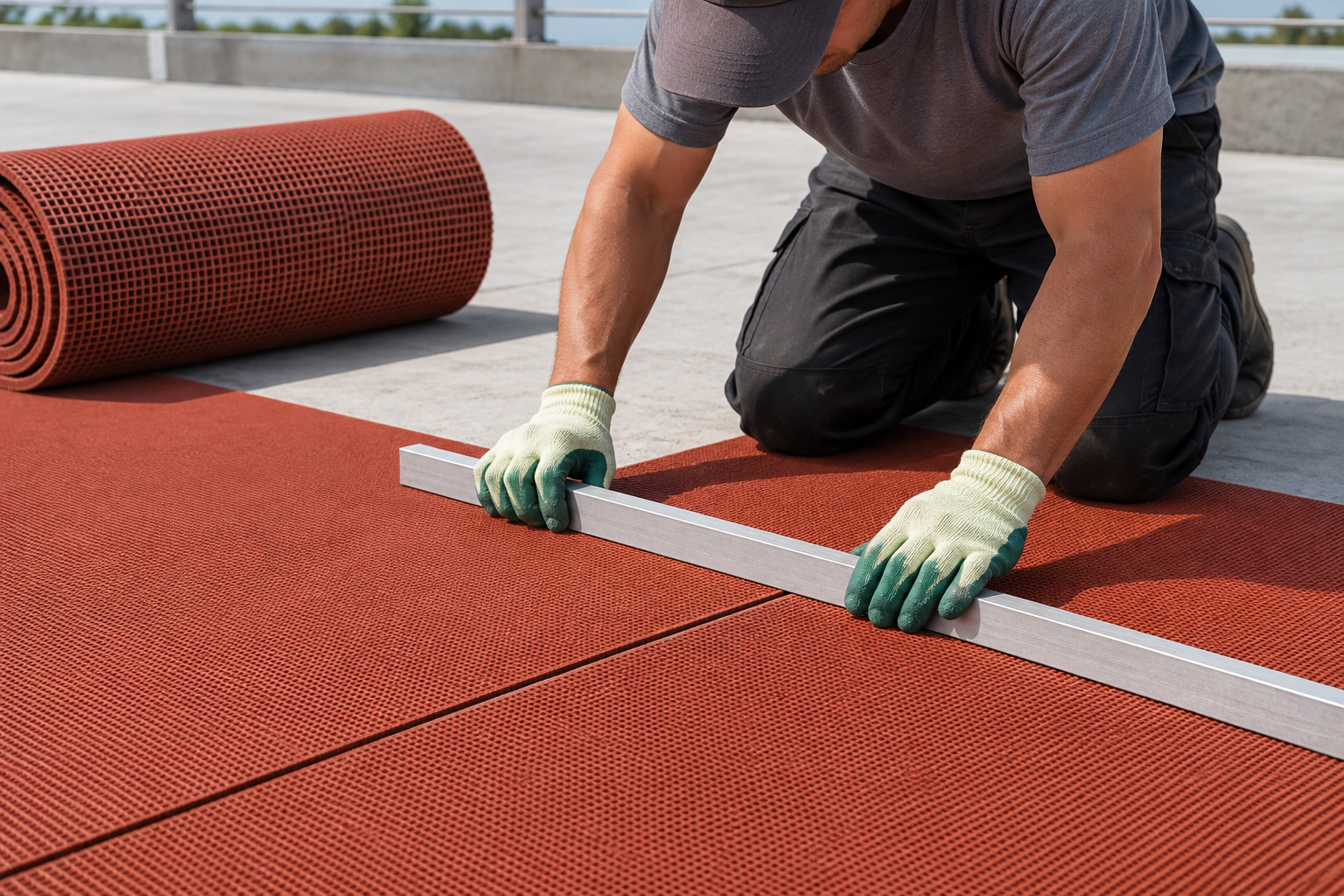
![Installer checking an end-joint alignment with a straightedge before final fitting]()
Figure 4. Installer checking an end-joint alignment with a straightedge before final fitting. AI-generated technical illustration.
Preserve Drainage and Movement Details
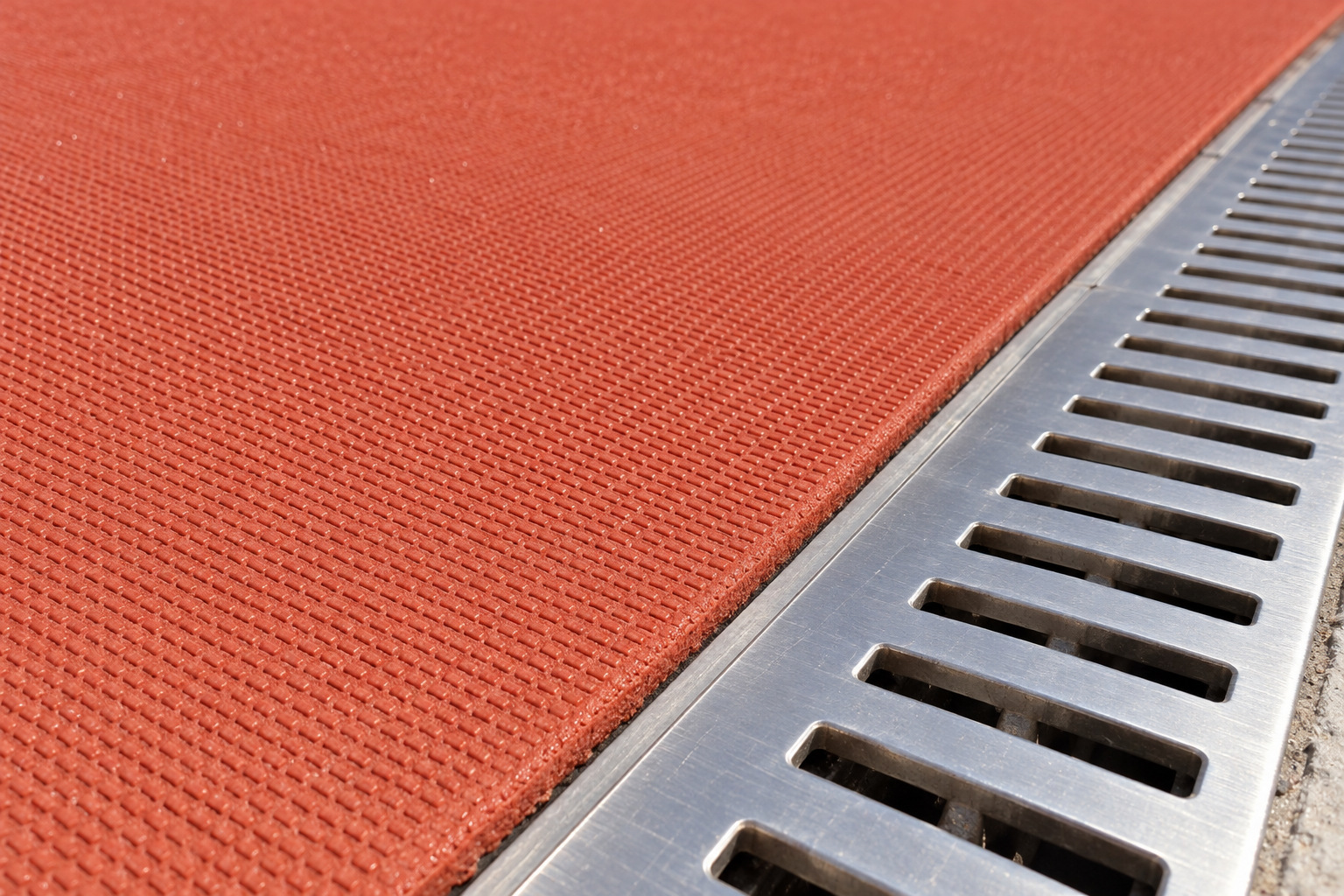
The rubber sheet should not bridge a structural movement joint unless the engineered detail explicitly allows it. Existing cracks require assessment before they are covered. At perimeter drains and curbs, avoid unsupported lips, adhesive obstruction and details that trap water beneath the surface.
After installation, check joints under natural light and verify that transitions are flush. Include the final roll map in the handover information. It helps future maintenance teams locate material boundaries, original lots and planned interfaces without guessing from the painted lane lines.
![Flush termination between a prefabricated rubber track and a linear drainage channel]()
Figure 5. Flush termination between a prefabricated rubber track and a linear drainage channel. AI-generated technical illustration.
Develop the Roll Plan With HUADONG
For a facility using GOTER prefabricated track, share the surveyed layout, radii, event areas and drainage details before ordering. Roll quantities and cutting allowances should follow the approved arrangement. The resulting plan connects factory-supplied material with the site's geometry and gives the installation team a clear sequence to execute.
Frequently Asked Questions
1. Must a sheet seam sit directly beneath a lane line?
Not universally. The approved layout and product instructions govern seam placement. Painted lane markings and sheet boundaries are different features.
2. Can a roll be stretched around a tight curve?
Use the manufacturer's approved curve-fitting method. Forcing a sheet into position can introduce stored stress or wrinkles and should not replace proper layout planning.
3. Should all end joints be staggered?
That depends on the system and approved detail. Staggering is not a substitute for bonding and support, and a generic rule may conflict with the intended installation method.
4. Can the surface cover a structural expansion joint?
Only according to an engineered detail that accommodates the movement. Simply bonding a continuous sheet over it can transfer stress into the surface.
5. Why keep a roll map after completion?
It records where material lots, joints and interfaces are located. That makes inspections, localized repairs and future replacement planning more precise.