From Design Coordinates to Site Control: How a Running Track Is Set Out Accurately
Accurate setting out converts a geometric design into physical points that every construction trade can use and later verify. For a standard 400 m track, the surveyor must distinguish the centre points, tangent points, inner kerb, measurement lines, lane boundaries and drainage interfaces. A single coordinate is not enough. Design data, control points, instrument checks, tape corrections, independent calculations and stage-by-stage remeasurement must form one traceable system.
![Surveyor establishing field control points for an accurate running track layout]()
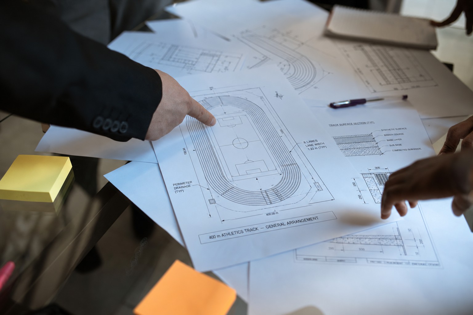
Figure 1. Setting out begins with a coordinated review of the current drawings, centre points, tangent points, lane definitions and construction interfaces. Photo: HUADONG project team.
Verify Design Data and the Survey Control Network
Before any point is marked on site, verify the coordinate system, elevation datum, centreline direction, centre points, tangent points and definitions of the inner and outer edges. Confirm the drawing revision. If the surveyor uses an old centre-point schedule while the drainage or stand layout has already changed, precise observations can still reproduce the wrong design.
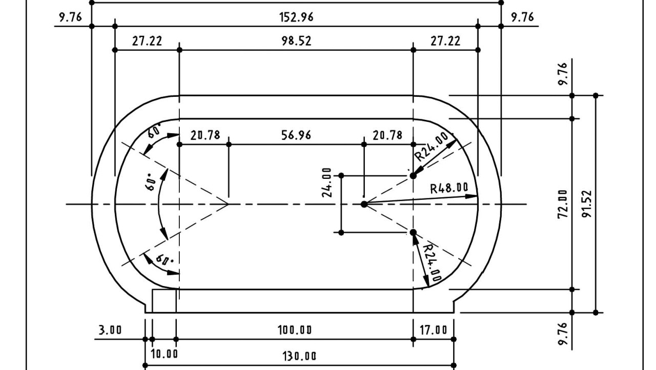
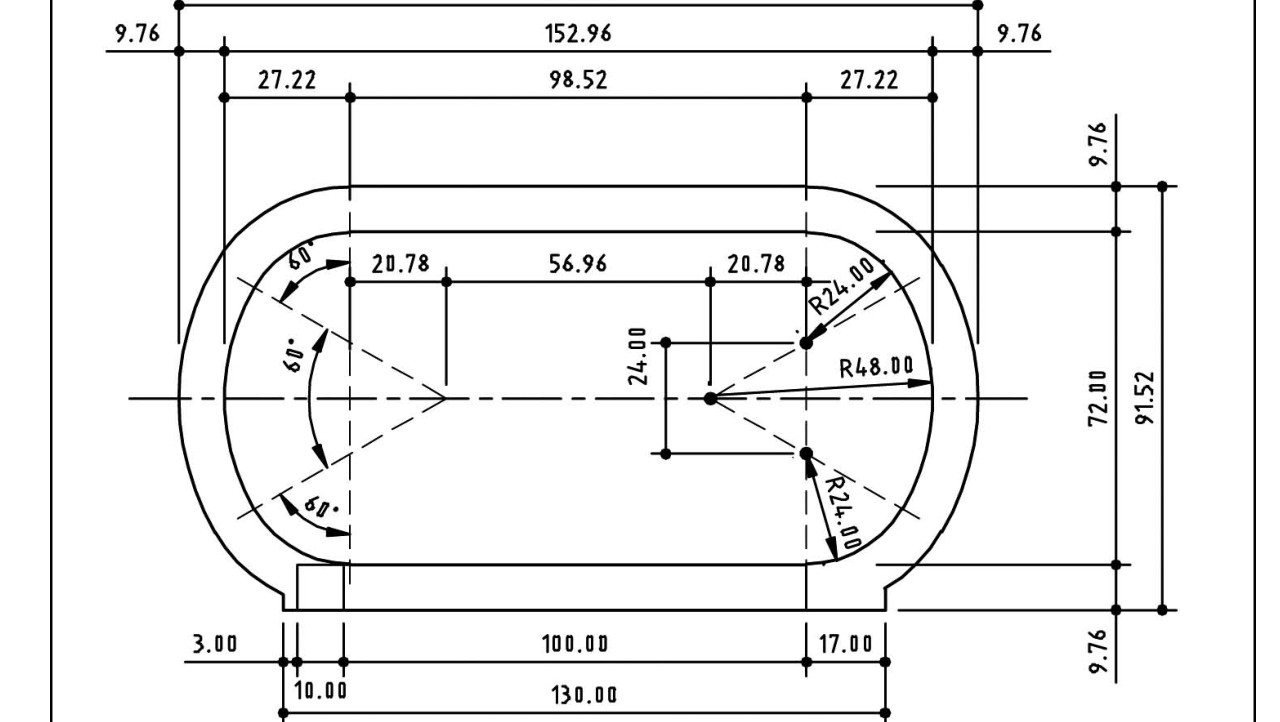
The typical standard geometry uses two straights of 84.390 m, a radius of 36.500 m to the outer face of the inner kerb and a lane-one measurement radius of 36.800 m, 0.300 m outside the kerb. Other lane measurement lines are 0.20 m from the outer edge of the adjacent inside lane. Nominal lane width is 1.22 m with an allowed deviation of plus or minus 0.01 m. The inner-edge length is 398.116 m and the nominal lane-one measurement-line length is approximately 400.001 m.
The basic rectangle A B C D may be checked from the two centre lines. The cited layout uses CP1 to CP2 and M1 to M2 distances of 84.390 m with a tolerance of plus or minus 0.002 m, an angle alpha of 25.9881 degrees and a distance of 91.945 m from the centre points to A, B, C or D on the inner edge. These relationships allow the geometry to be reconstructed and independently checked.
Control points can move during clearing, earthworks and construction traffic. Before setting out, perform an independent check by distance, angle or level and record the instrument, date, observation conditions and result. Place primary points outside the construction disturbance zone and provide secondary points from which the original geometry can be restored.
![Track design drawing checked against site control coordinates before construction]()
Figure 2. A track layout diagram shows how centre points, radii, straights and overall site dimensions relate to one geometric model.
Set Out the Key Geometry and Record Every Point
After the control network is confirmed, set out the centre points, straight axes, tangent points, inner kerb control points, lane boundaries and drainage references. Every peg, nail or paint mark needs an unambiguous name. The same location may represent a centreline, structural edge, marking edge or channel centre, so the setting-out sheet must state which object the point controls.
The cited measurement procedure uses 28 control readings. The prerequisite is a centre-point distance of 84.39 m plus or minus 0.005 m. Points 1 to 12 and 14 to 25 provide 24 radius measurements of 36.50 m plus or minus 0.005 m, with 12 points on each semicircle at approximately 10.42 m intervals along the arc. Readings 13 and 26 are the two 84.39 m straight sections, while 27 and 28 control straight alignment with an allowed error of 0.010 m.
The control readings must be recorded rather than replaced by a visual statement that the track is smooth. The average deviation must not exceed plus 0.040 m and must not be negative. The calculated average track length should be no less than 400.00 m and no more than 400.040 m under the cited procedure. A curve that looks regular can still have a shifted centre or incorrect radius.
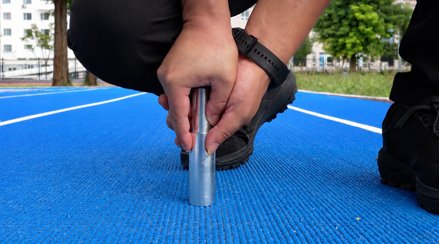
Centre points should be permanently marked with corrosion-resistant metal tubes. The cited construction uses a 12 mm tube extending 0.15 m above the foundation, protected by a 0.04 m sleeve. The foundation is at least 0.20 m in diameter and extends at least 1.00 m below the frost-free layer. Long-term protection is essential because later stages and final certification may need to recover the same centre.
Apply Independent Geometry and Measurement Checks
The geometric model should survive reverse calculation. Confirm that the centre line between the two semicircles agrees with the design axis, each straight is tangent to the curve, the two straights are equal and lane widths remain continuous. One person should generate the coordinates and another should independently calculate them from the centre, radius, axis and tangent relationships.
For a centre at Xc Yc and a measured point Xi Yi, the radial residual is the measured centre-to-point distance minus the theoretical radius. A single residual of plus 18 mm with neighbouring points near zero suggests a local point or structure issue. Five consecutive residuals of plus 16 to plus 19 mm suggest a systematic centre or radius shift. Grouping similar points is more informative than inspecting each reading in isolation.
Steel-tape measurements require temperature and tension control. The cited procedure applies 50 N to a 30 m tape and 100 N to 50 m and 100 m tapes. Measure the tape temperature immediately before and after use. The correction is the temperature difference from 20 degrees Celsius multiplied by the measured length and 0.0115 mm per metre per degree. At 15 degrees Celsius over 36.50 m, the reading is increased by approximately 2 mm to 36.502 m. A tape containing 36% nickel may be used without this temperature correction under the cited guidance.
![Finish-line geometry and lane reference points marked for a standard athletics track]()
Figure 3. Field measurement must identify the exact surface or structure being checked and preserve the point number, design value and measured result. Photo: HUADONG project team.
Recheck by Construction Stage and Protect the Controls
Setting out is not a one-time activity. After earthworks, check the main axes and broad levels. After base construction, remeasure the inner edge, tangent transitions and critical cross-sections. Before surfacing, confirm the formed geometry. After surfacing, complete the as-built geometry before final marking. The final measured shape, not an assumed design shape, is the correct input for precise line marking.
Different trades need different control densities. Earthwork crews use boundary and rough-setting points, base crews need closer elevation control, surfacing crews need a verified finished base and marking crews require final geometry. The project method statement should define what is checked at each stage instead of applying one tolerance indiscriminately to every operation.
Construction traffic, material storage and temporary fencing can block sightlines or disturb points. When a primary point is lost, restore it from protected secondary control and record the new network adjustment. Do not extend new points from an already constructed track edge without checking back to the control network.
![Running track layout geometry showing coordinated straights, curves and control points]()
Figure 4. Start and finish lines depend on the final measured geometry and must be laid out from verified control, not from visual alignment alone. Photo: HUADONG project archive.
Key Dimensions and Calculation Checks
• Typical standard geometry: two straights of 84.390 m; inner-kerb outer-face radius 36.500 m; lane-one measurement radius 36.800 m.
• Measurement offsets: lane one 0.300 m outside the inner kerb; other lane measurement lines 0.20 m from the adjacent inside-lane outer edge.
• Lane width: nominal 1.22 m with an allowed deviation of plus or minus 0.01 m; line width must be assigned to the correct lane boundary.
• Inner-edge length: 398.116 m; lane-one measurement-line length approximately 400.001 m.
• Basic rectangle check: centre-point distance 84.390 m plus or minus 0.002 m; angle alpha 25.9881 degrees; centre point to A B C or D distance 91.945 m.
• Twenty-eight control readings: 24 radii of 36.50 m plus or minus 0.005 m, two straights of 84.39 m plus or minus 0.005 m and two straight-alignment checks with 0.010 m tolerance.
• Track-length result: calculated average no less than 400.00 m and no more than 400.040 m under the cited procedure.
• Tape tension: 50 N for a 30 m tape; 100 N for 50 m and 100 m tapes.
• Tape temperature correction: temperature difference from 20 degrees Celsius x measured length in metres x 0.0115 mm; add the correction below 20 degrees and subtract it above 20 degrees.
• Control-point record fields: point number, design X Y H, measured X Y H, plan difference, elevation difference, instrument, date, observer and checker.
Reference basis: 400 m track geometry, tape measurement and temperature correction are drawn from Section 2.2.1.1 of the Track and Field Facilities Manual, Fourth Revised Draft. The 28 control readings, centre markers and track-length criteria are drawn from Section 2.2.1.4. Confirm the applicable edition, project specification and responsible authority's acceptance procedure before using these figures contractually.
Key Controls and Handover Deliverables
The setting-out record should preserve design coordinates, calculated coordinates, field coordinates and differences. Each point must identify the drawing revision, structure or line controlled, elevation, observation method and protection status.
Independent checks should use a different station, observation route or calculation method. Repeating the same data through the same calculation is not an independent verification. When a discrepancy is found, check the instrument and conditions first, then the control network and calculations, and finally the constructed work.
Stage handover records should state which points remain usable, which were replaced and which areas require correction. Keep the original reading and the post-correction reading. This evidence prevents a later adjustment to the line marking from hiding a structural geometry problem.
For a prefabricated surface, the verified base geometry should be approved before rolls are installed. Product uniformity does not remove the need for accurate site control. The HUADONG GODER prefabricated rubber running track must still be bonded to a base whose axes, levels and curve transitions have been measured and accepted.
Frequently Asked Questions
1. Why is one centre-point coordinate not enough for setting out?
The complete model also needs the second centre, axis direction, tangent points, edge definitions, lane offsets and elevation datum. These relationships provide independent checks.
2. What is the purpose of the 28 control readings?
They quantify the two semicircles, two straights and straight alignment so that the track length and shape can be checked as a complete system.
3. When should the track be remeasured?
Remeasure after earthworks, after base construction, before surfacing and after the finished surface is complete. Final marking should use the as-built geometry.
4. What should happen if a control point is disturbed?
Restore it from protected secondary control, complete a new network check and record the relationship between the old and new results before continuing construction.
Keywords: running track setting out; 400 m track geometry; survey control network; track construction surveying; athletics track measurement.