Accurate Track Geometry Still Requires Elevation and Drainage Control
A running track can be correct in plan and still perform badly if its elevation and drainage system are not coordinated. Surface gradients, the inner drainage channel, collection boxes, underground pipes and the final outfall must form one continuous hydraulic path. A correct spot level does not prove that water can leave the venue. The design and construction teams need a common elevation datum, a documented direction of fall and layer-by-layer measurements that connect the finished surface to every drainage node.
![Surveyor checking the elevation and drainage level beside a running track channel]()
Figure 1. A site technician checks the level and position of a drainage channel before the running-track surface is installed. Photo: HUADONG project team.
Establish One Elevation Datum for the Entire Venue
Vertical design starts with a shared datum. Survey control points, track design levels, road levels, stand interfaces, landscape grading and the municipal drainage connection must all refer to the same elevation system. If one discipline works from a different benchmark, a drawing can look correct while the constructed interface is several centimetres out of position.
The first drainage questions are simple but decisive: where does the water originate, which surface collects it, where is the lowest point and what level is available at the final connection? External runoff from roads, stands or higher surrounding ground should be intercepted before it enters the track. If the external pipe connection is too high, water may reach the channel but still have no gravity route out of the venue.
The cited design basis uses a rainfall estimate of 120 L/s/ha and applies a runoff coefficient according to the surface. Typical coefficients include 0.9 for an impermeable synthetic surface, 0.5 for a permeable synthetic surface, 0.5 for a non-synthetic mineral surface, 0.5 for artificial turf, 0.25 for natural turf, 0.6 for paved roads, 0.3 for water-absorbing roads and 0.8 for asphalt roads. Catchment area multiplied by rainfall intensity and the relevant coefficient becomes the design input for channels, boxes and pipes.
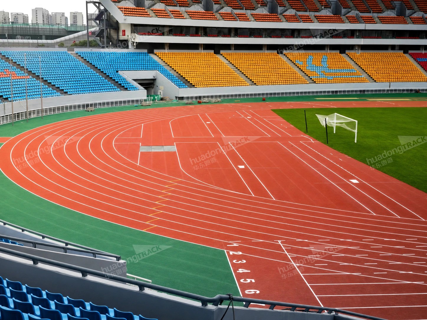
![Completed athletics track demonstrating coordinated surface levels and drainage]()
Figure 2. A completed athletics venue shows why the track, infield, drainage line and surrounding circulation areas must be coordinated within one elevation system. Photo: HUADONG project archive.
Coordinate Surface Slopes with the Drainage Path
For track events, the downward longitudinal gradient in the running direction must not exceed 0.1%, while the crossfall toward the inside lane must not exceed 1.0%. A design crossfall slightly below 1.0% is strongly recommended so that construction tolerances do not push the completed surface beyond the limit. The inner kerb of a standard 400 m track should remain level, and slope measurements on a sprint straight should be taken directly between the relevant start and finish lines.
Gradient must be calculated from measured levels and horizontal distance, not judged by eye. The basic expression is i = delta H / L x 100%. A 50 mm difference over 10.00 m gives a gradient of 0.50%. Across an 8.00 m track width, a 1.0% crossfall corresponds to 80 mm. Along 40.00 m, a 0.1% longitudinal gradient corresponds to only 40 mm. These small differences explain why an apparently flat area can still contain a local basin.
The design should issue a level schedule for the inner and outer track edges, tangent points, channel top, channel invert, inlets and access points. Construction surveying should then produce longitudinal and cross sections. If a local low point is offset from the nearest inlet, the surface may hold water even when every individual spot level appears close to its design value.
Design Channels Inlets Boxes and Outfalls as One System
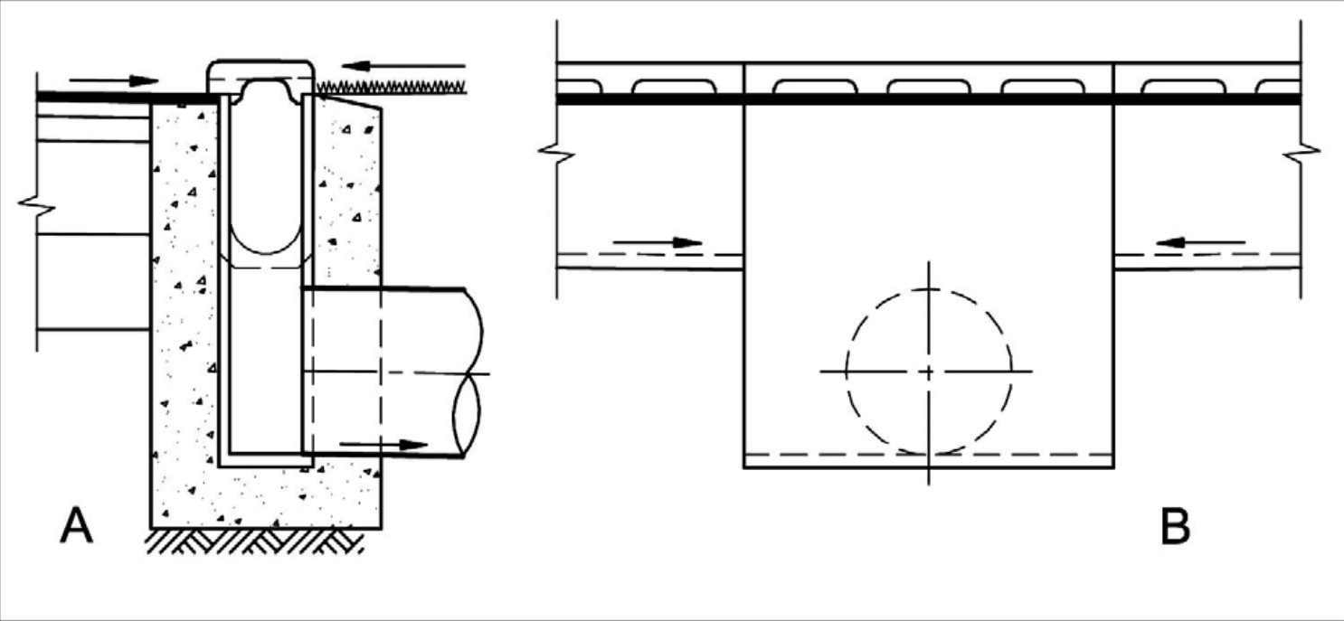
A perimeter channel is normally arranged as a ring around the track. In the cited reference, each channel section is approximately 33.00 to 35.00 m long and connects through six to eight collection boxes to the collector pipe. A collection box is typically 0.50 m long, the same width as the channel top and fitted with a sand trap. The channel top controls the smoothness of the track edge, the channel invert controls flow to the box and the pipe connection controls whether water can leave the site.
The channel is described as a polyester hollow unit with a removable cover and a nominal cross-section of 125 mm. Where the top edge of the cover is not level with the adjacent surface, the edge should be rounded to a radius of at least 20 mm to reduce the trip hazard. The channel foundation commonly uses concrete with a minimum compressive strength of 15 N/mm2, a base depth of at least 200 mm and bottom support at least 80 mm thick.
Inlet openings must match the direction from which water enters. The cited slot width is 10 to 15 mm for water entering from above and 10 to 25 mm for water entering from the side. A single inlet pipe has a slot height of 10 to 25 mm and an inlet area of at least 0.001 m2. Maximum inlet spacing is 2.50 m beside an impermeable synthetic surface and 5.50 m beside a permeable synthetic or mineral surface.
![Cross-section detail of the inner drainage channel and running track edge]()
Figure 3. Typical channel and collection-box sections illustrate how the top edge, invert and pipe connection form one drainage node.
Control External Water and Underground Drainage
A low-lying venue cannot solve all water problems with local surface grading. Runoff and groundwater from higher external areas should be intercepted and directed to a receiving basin before they enter the stadium. Roads, stands and landscaped areas must be included in the catchment analysis, and maintenance access must allow collection boxes and inspection chambers to be cleaned.
For underground drainage, the cited trench-bottom width is b = d + 2 x 70 mm, where d is the pipe diameter and 70 mm clearance is provided on each side. Drains are placed perpendicular to the ground slope. Where the track is more than 5.00 m wide, the drain is located near the centre, with typical channel spacing of 6.00 to 7.00 m depending on rainfall and soil permeability. The non-synthetic base layer and drainage backfill should provide water absorption above 0.0001 m/s.
The surrounding surface-water pipe is designed with a minimum gradient of 0.3% and a maximum of 0.5%. Closed pipes should maintain a flow velocity between 0.50 and 3.00 m/s. Inspection chambers are installed along collector and closed pipelines, at changes in gradient or direction, with spacing not exceeding 110.00 m and a minimum diameter of 1000 mm under the cited reference.
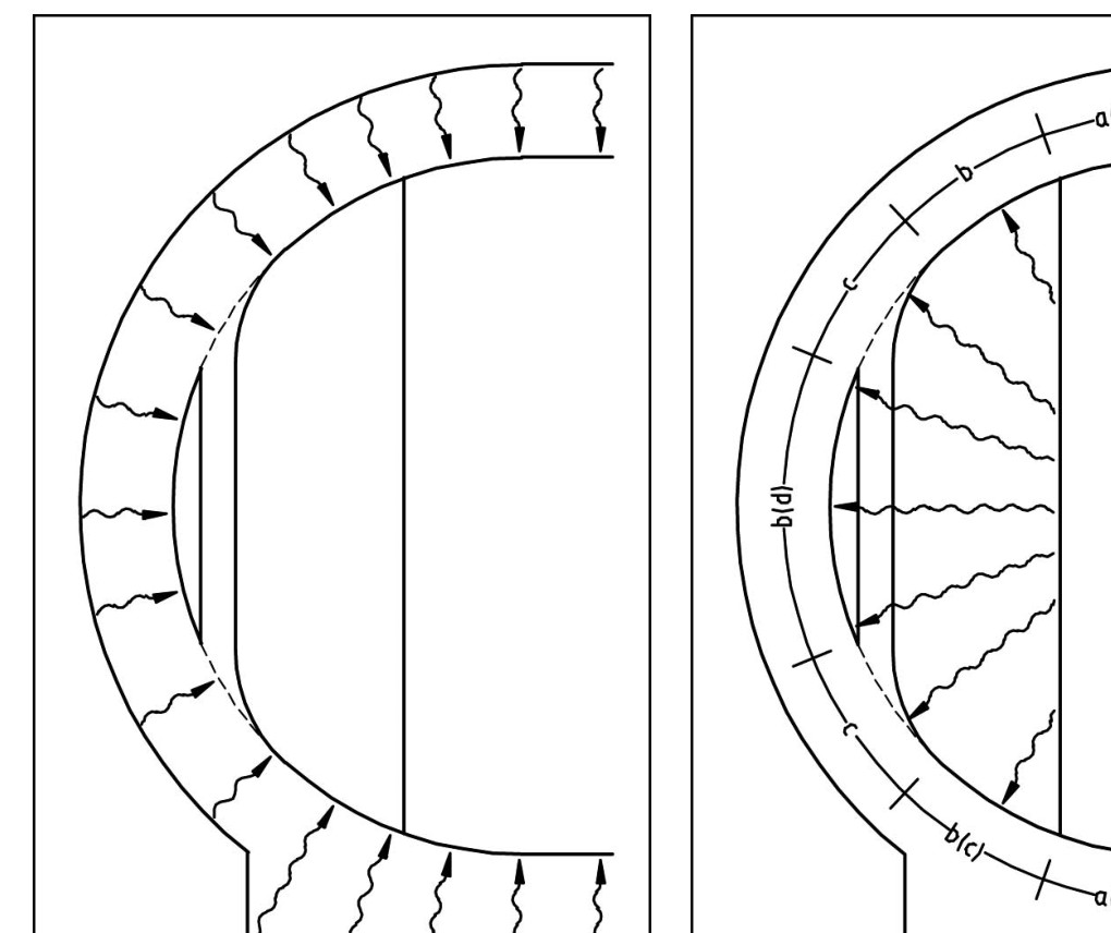
![Running track drainage direction diagram showing the complete surface-to-outfall path]()
Figure 4. Drainage directions around the bend and semicircular areas must lead continuously toward the perimeter channel and collection system.
Verify Elevation Layer by Layer
Elevation control should follow the construction sequence. Measure after subgrade shaping, after base construction, before surfacing and again after completion. Layer-by-layer records make it possible to identify where an error entered the work. Discovering ponding only after the finished surface is installed can lead to repairs that affect appearance and performance without correcting a deeper structural problem.
Office processing should produce two views. The first is a point schedule showing design level, measured level and difference by section. The second is a plan-based difference map that reveals continuous low bands. An isolated deviation near a cover or channel edge should be checked as a local detail; a continuous low side around an entire bend may indicate a datum, base-forming or outlet-level problem.
For prefabricated rubber systems, the base must already provide the required geometry, crossfall and drainage path before rolls are bonded. A factory-controlled roll cannot compensate for a systematic low area in the base. This is why the base acceptance records should be complete before installing the HUADONG GOTER prefabricated environmental rubber track or another prefabricated surface system.
Key Dimensions and Calculation Checks
• Track gradients: downward longitudinal gradient in the running direction not more than 0.1%; crossfall toward the inside lane not more than 1.0%; design crossfall preferably below 1.0% to retain tolerance.
• Gradient calculation: i = delta H / L x 100%. A 0.05 m fall over 10.00 m equals 0.50%.
• Perimeter channel: sections approximately 33.00 to 35.00 m long, connected through six to eight collection boxes; each box typically 0.50 m long and fitted with a sand trap.
• Channel section: nominal 125 mm; concrete base minimum 15 N/mm2; base depth at least 200 mm; bottom support at least 80 mm thick.
• Inlet slots: 10 to 15 mm for top entry and 10 to 25 mm for side entry; inlet area at least 0.001 m2.
• Underground drainage: trench bottom b = d + 140 mm; typical spacing 6.00 to 7.00 m; absorption of the base and drainage backfill above 0.0001 m/s.
• Pipe gradients and flow: 0.3% to 0.5% for the surrounding surface-water pipe; closed-pipe flow velocity 0.50 to 3.00 m/s.
• Pipe sizes by cited catchment range: 65 mm intake pipe; 100 mm up to 3500 m2; 125 mm for 3501 to 5000 m2; 150 mm for 5001 to 7500 m2; 200 mm for 7501 to 15000 m2.
• Inspection chambers: spacing not more than 110.00 m, minimum diameter 1000 mm, and additional chambers at changes in direction or gradient.
Reference basis: slope and safety-zone provisions are drawn from Sections 2.1.3, 2.2.1.2 and 2.2.1.5 of the Track and Field Facilities Manual, Fourth Revised Draft. Surface-water drainage provisions are drawn from Sections 3.3.2 to 3.3.4, and underground drainage from Sections 3.4.2 to 3.4.4. Confirm the applicable edition, local drainage code and approved project drawings before using these figures for design or acceptance.
Key Controls and Handover Deliverables
The handover package should show the benchmark, control points, direction of calculation and complete path from surface level to final outfall. Each record should include start and end levels, horizontal distance, calculated gradient, intended flow direction and acceptance basis.
Survey points should cover straights, bends, tangent points, inner and outer edges, inlets, channel inverts, collection boxes and the external connection. Do not infer drainage performance from only the highest and lowest point on the site.
Drainage design calculations, as-built levels and post-rain observations answer different questions. The design predicts flow, the survey confirms constructed geometry and observation checks actual behaviour. Record rainfall conditions, blockage or construction debris before attributing ponding to the track surface.
When a discrepancy is found, remeasure a continuous section on both sides of the node, identify the responsible construction layer, complete the correction and repeat the survey. Preserve the original and corrected results so the final evidence chain remains traceable.
Frequently Asked Questions
1. Why can a track pond even when its average gradient is correct?
Average gradient can hide a local basin, reverse fall or inlet that is positioned above the actual low point. Continuous longitudinal and cross-section measurements are needed.
2. Should the finished surface be used to correct major base-level errors?
No. The base should provide the designed levels and drainage path. Using the surface as a levelling layer can create variable thickness and still leave a system-level drainage defect.
3. What should be checked at the external drainage connection?
Confirm the connection level, available fall, pipe capacity, direction of flow and whether external water can back up into the venue.
4. What records are needed before prefabricated track installation?
Retain the approved level schedule, base survey, gradient calculations, channel and inlet measurements, outlet confirmation, defect records and reinspection results.
Keywords: running track drainage; track elevation control; surface gradient; stadium drainage system; prefabricated rubber track base.